|
|
Order by: Available to: eBay Affiliate Links
|

Buy It Now
$113.42 Shipping Condition: Used Location: Farmingdale, United States Hughes Aircraft Company Model 8010H15F000(S/N# 107) 8– 18GHz TWT(Traveling Wave Tube) Power Amplifier rated at 10-Watts(min) power output. It has type“SMA” ... morefemale RF Connectors for RF input and output and these connectors are located on the front panel. This unit also has an(optional? coaxial ferrite isolator installed at the TWT output port to isolate the tube against high reflections caused by a highly reflective load or operation when un-terminated. This unit is beautifully constructed with the best parts available in America at the time and reflects a lot of pride in workmanship as well as careful consideration of the design. The above description is a“best effort” so BID ACCORDINGLY. I am selling this item for parts or repairs due to the fact that this amplifier MAY OR MAY NOT meet its output power specification of 10 Watts minimum across the full band of 8– 18GHz. Using a 20dB directional coupler rated at 7.5– 18GHz with a medium power termination on the thru line. Along with a leveled sweep generator and a spectrum analyzer I made some crude measurements to show that this item does function. Disregarding calibration variations of the instruments from absolute and assuming 1dB loss across the frequency range for both the input and output RF cables, I have some gain/ Pout measurements at 1GHz steps across the 8– 18GHz frequency range. Also, I put the spectrum analyzer on MAX HOLD to display an output power sweep. With the Pin set to +3.5 dBm(+2.5dBm considering input cable loss) I come up with the following gain and Pout VS Frequency(remember. I am adding 21 dB Coupler factor + output cable Insertion loss to the data measured on the spectrum analyzer) The result is: 8GHz G= 35.95dB Pout= +38.5dBm. 9GHz G= 36.45dB Pout= +39dBm, 10GHz 35.28dB Pout= +37.83dBm; 11GHz G= 34.62dB Pout= +37.17dBm, 12GHz G= 33.45dB Pout= +36dBm, 13GHz G= 33.28dB Pout= +35.83dBm, 14GHz G= 32.45dB Pout= 35dBm, 15GHz G= 36.78dB Pout= +39.33dBm, 16GHz G= 36.78dB Pout= 39.33dBm, 17GHz G= 35.12dB Pout= +37.67dBm, 18GHz G=
Buy It Now
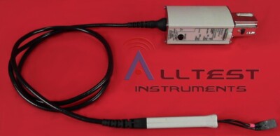
$43.74 Shipping Condition: Used Location: Farmingdale, United States TEK P7313 with complete accessories in carrying case. Mint condition. Good luck! DESCRIPTION 12.5 GHz Z-Active(TM) Differential Probe for use in applications ... moresuch as PCI-Express I& II. Serial ATA II, USB 2.0, DDRII, Rambus, XAUI, etc. The Z-Active architecture is a hybrid approach composed of a distributed attenuator topology feeding an active probe amplifier. The Z-Active probes use a tiny passive probe tip element that is separate from the amplifier, extending the usable reach of the probe. In traditional active probes, adding this much length can introduce signal fidelity problems. However this architecture maintains high DC input resistance and presents a higher AC impedance than previous probe architectures. It accomplishes this while providing significant length between the probe body and the probe attachment point to the DUT. This architecture provides the best of both worlds: high DC impedance like existing active probes and the stable high frequency loading of Z0 probes. Signal Fidelity Z-Active architecture provides: High bandwidth Excellent step response Low loading High CMRR Connectivity This family of probes uses Tip-Clip(TM) assemblies. An interchangeable probe tip system that enables customers to configure their probe with the optimal tip for their application. These detachable assemblies make it possible to replace a tip for a fraction of the cost formerly associated with such hardware changes. The several lengths and variable spacing of the assemblies provide flexibility for adapting to vias and other test points of differing sizes. With Tektronix Tip-Clip assemblies, Monday?s solder-in probe can become Tuesday?s handheld tool, simply by switching tips. The Z-Active probe design allows the probe to easily switch between solder, handheld, or fixtured applications.
Buy It Now
Free Shipping Condition: New Location: China Assembled semi-finished rectifier filter board (not contain capacitance). Circuit board with double-sided blue glass plate thickness of 1.6mm, double-sided ... moretinplate oil plate, wiring reasonable. Output with two LED lights.
Buy It Now
Free Shipping Condition: New Location: China Assembled semi-finished rectifier filter board (not contain capacitance). Circuit board with double-sided blue glass plate thickness of 1.6mm, double-sided ... moretinplate oil plate, wiring reasonable. Output with two LED lights.
Buy It Now
Free Shipping Condition: New Location: China Assembled semi-finished rectifier filter board (not contain capacitance). Circuit board with double-sided blue glass plate thickness of 1.6mm, double-sided ... moretinplate oil plate, wiring reasonable. Output with two LED lights.
Buy It Now
Free Shipping Condition: New Location: China Assembled semi-finished rectifier filter board (not contain capacitance). Circuit board with double-sided blue glass plate thickness of 1.6mm, double-sided ... moretinplate oil plate, wiring reasonable. Output with two LED lights.
Buy It Now
$3.00 Shipping Condition: New Location: China Tube Model: TIP41C. Electorlytic capacitor: high capacity. Model: 1969 small group A. Adjust Resistance: Sealed multi-turn adjustable resistance. Power ... moresource: DC 12-30V. Current Static: Standard 25 v DC to 0.8-0.9A.
|
|
|
 |